Compact Solar Repeater with Display
This guide walks you through assembly of a super compact, solar repeater using a Heltec T114, with minimal-to-no soldering required. A perfect first repeater build for someone with a nice 3D Printer.
Time Required: Approx 60 minutes
Prerequisites: 3D Printer, basic tools, soldering kit
Total Cost: ~$80-100
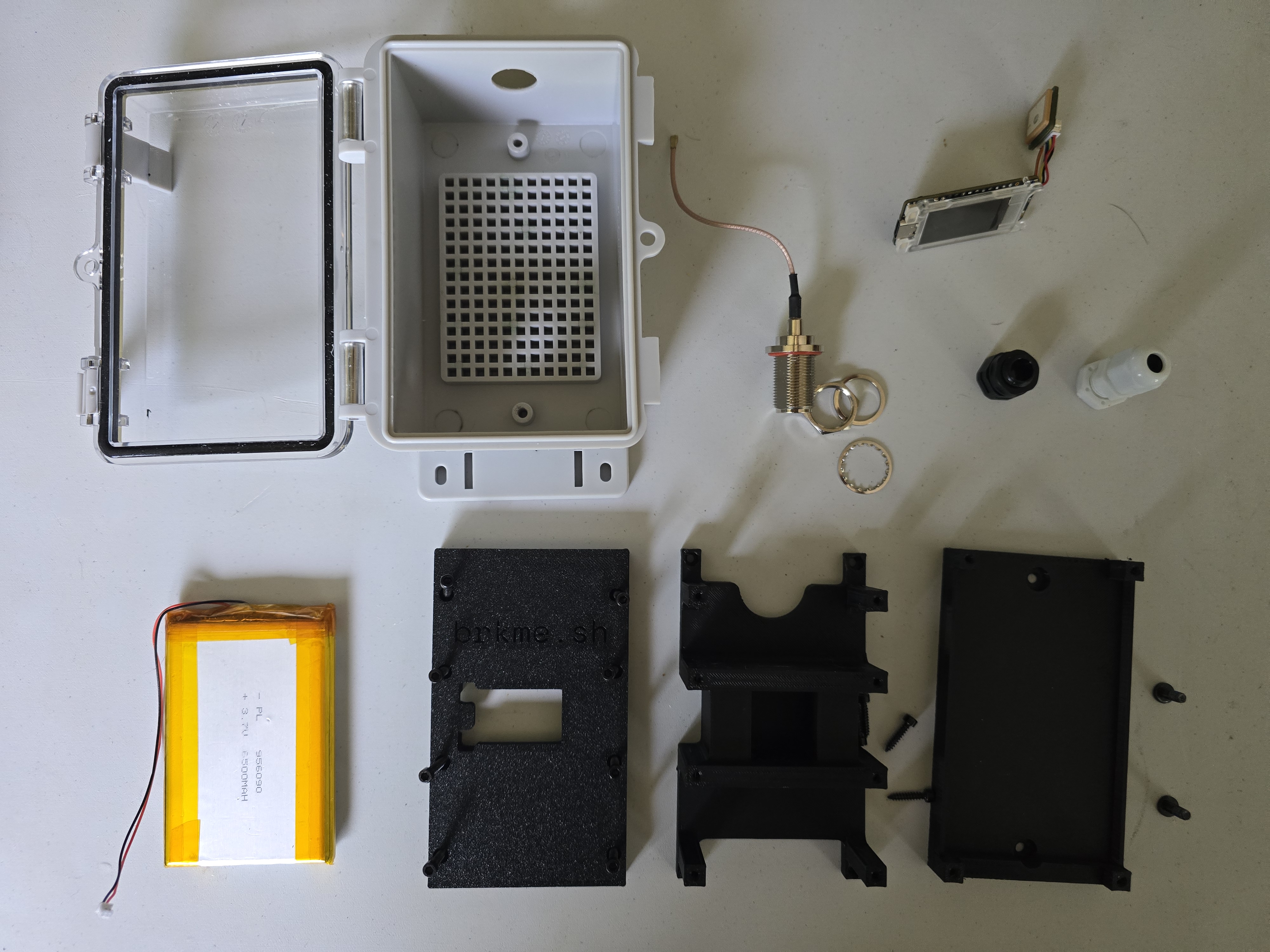
Required Components
- Heltec T114 — Core LoRa node
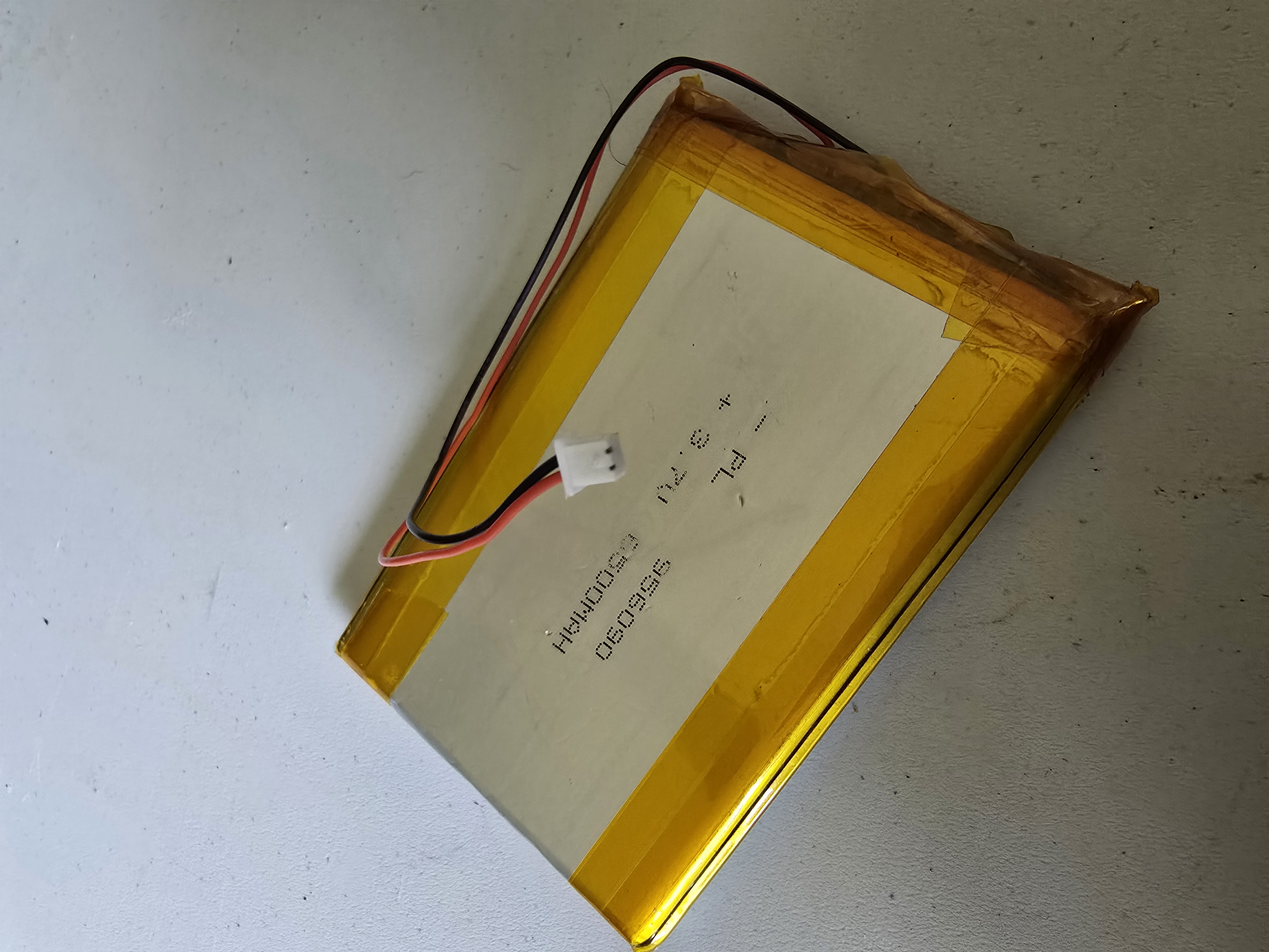
- 6500mAh LiPo Battery (JST PH2.0) — Reserve power
- USB-C Solar Panel (6W+) — Direct charging via USB-C port
- IPEX to Type-N Adapter + Cable — External antenna connection
- 5.8dBi Type-N Antenna — High-gain external antenna
- Waterproof Enclosure (IP65+) — Specifically the AliExpress model for these 3D Prints
- Waterproof Cable Gland (USB-C) — Sealed cable entry
- Pressure Relief Valve — Allows air out without letting moisture in.
- 100% Silicone Caulk — Ensures waterproofing around glands and valves.
- Polyimide Heat Tape — Useful for wrapping battery or cables inside the enclosure for safe attachment.
- Step Drill Bit — Significantly easier for drilling the plastic enclosure.
- Marine Heat-Shrink Tubing — Helps tidy cables and add thickness to cables through glands.
- Double Sided Tape — Secures battery to carriage if there is extra space.
- Metric Screw Kit — M3 fits the common 5x5 grids in these waterproof enclosures, and M4 fits the predrilled holes.
Optional Supplies
Instructions
-
Print STLs and change battery connector.
Print all three layers for inside the enclosure. You can download the 3D models at the bottom of this page and slice them to print on your printer. No supports needed, and 10-15% infill should be plenty.
The Heltec T114 comes with a smaller JST PH1.0 wire, which is needed to connect the battery directly to the board. If you are confident with soldering, you can remove the pre-attached PH2.0 connector and attach the PH1.0 instead. If you are not confident with soldering, I suggest finding an adapter or crimnping on a PH1.0 connector.
-
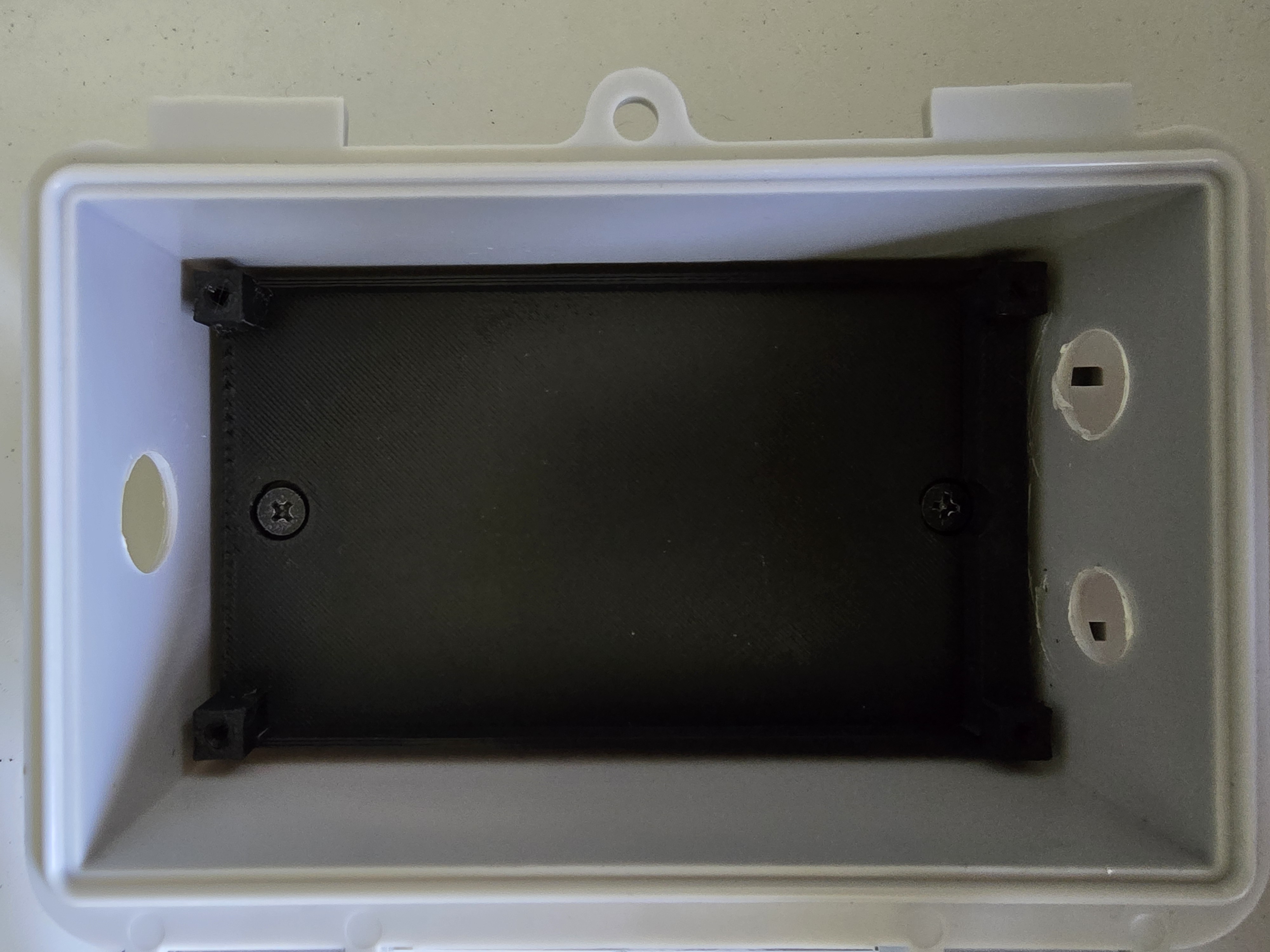
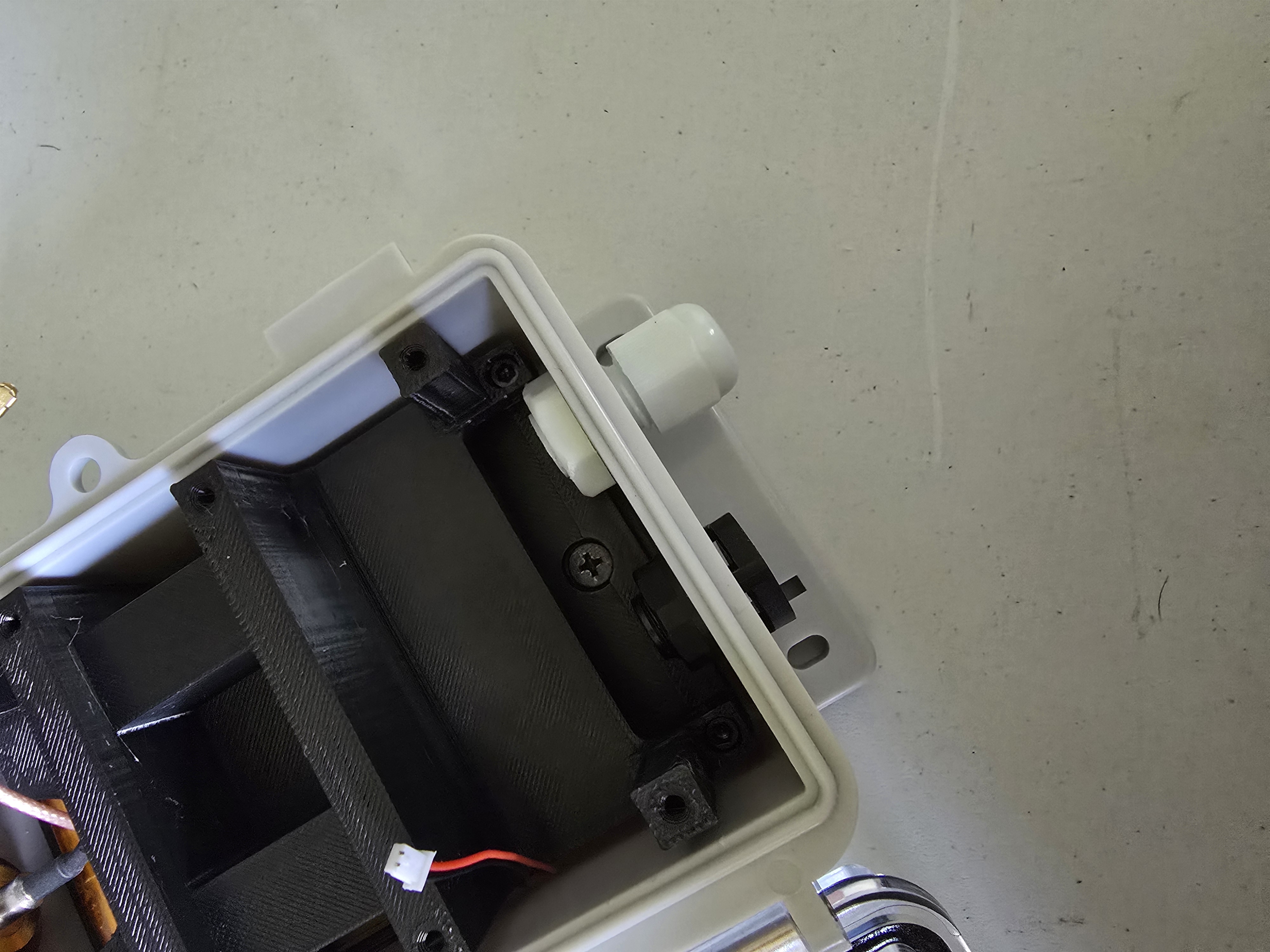
Install Battery Layer Print and Battery.
Screw the "Battery Layer" print into the enclosure with two M4 screws. Insert the battery and optionally use thin double-sided tape to secure in place. Feed the cable to the left side.
-
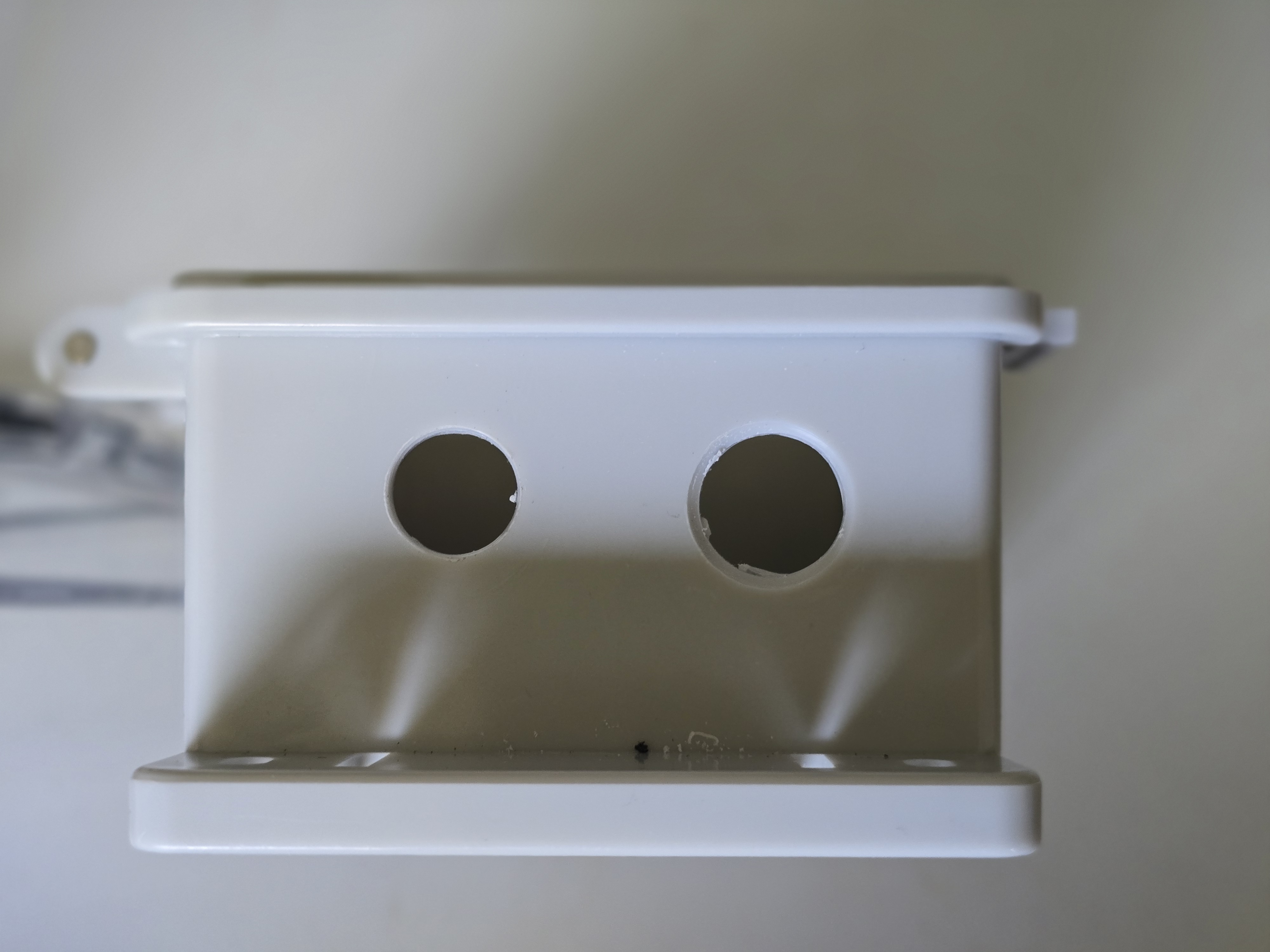
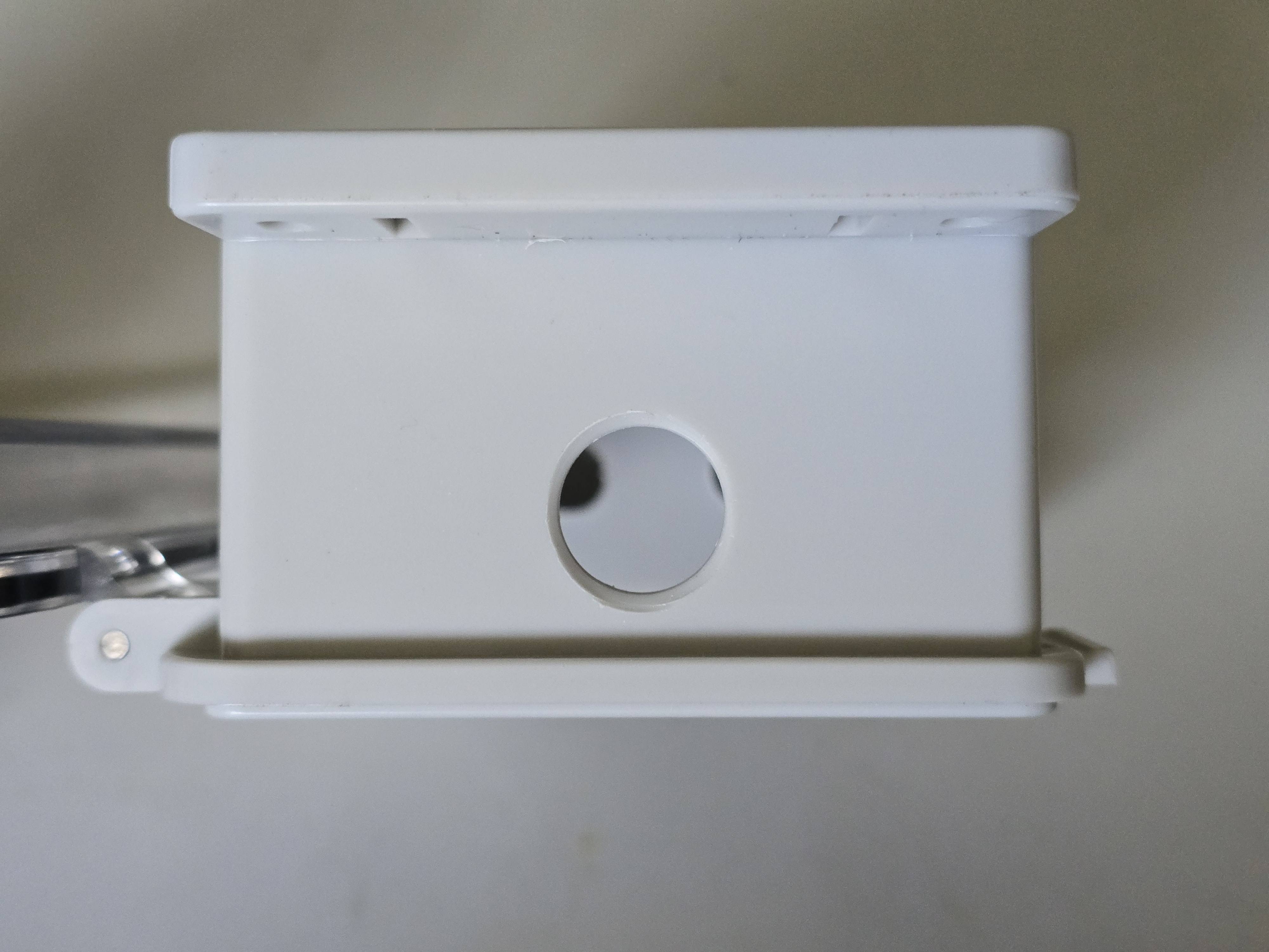
Prepare the Enclosure.
Drill three holes in your waterproof enclosure, insert passthrough items:
- Top hole (16mm): For the Type-N bulkhead antenna adapter
- Bottom holes (12mm, 13-14mm): For the USB-C cable gland and pressure relief valve.
Install the Type-N bulkhead adapter on top and thread the cable gland and valve into the bottom holes. Seal with silicone if needed for extra protection. Leave the outer section of the cable gland disassembled until the solar panel cable is fed through.
-
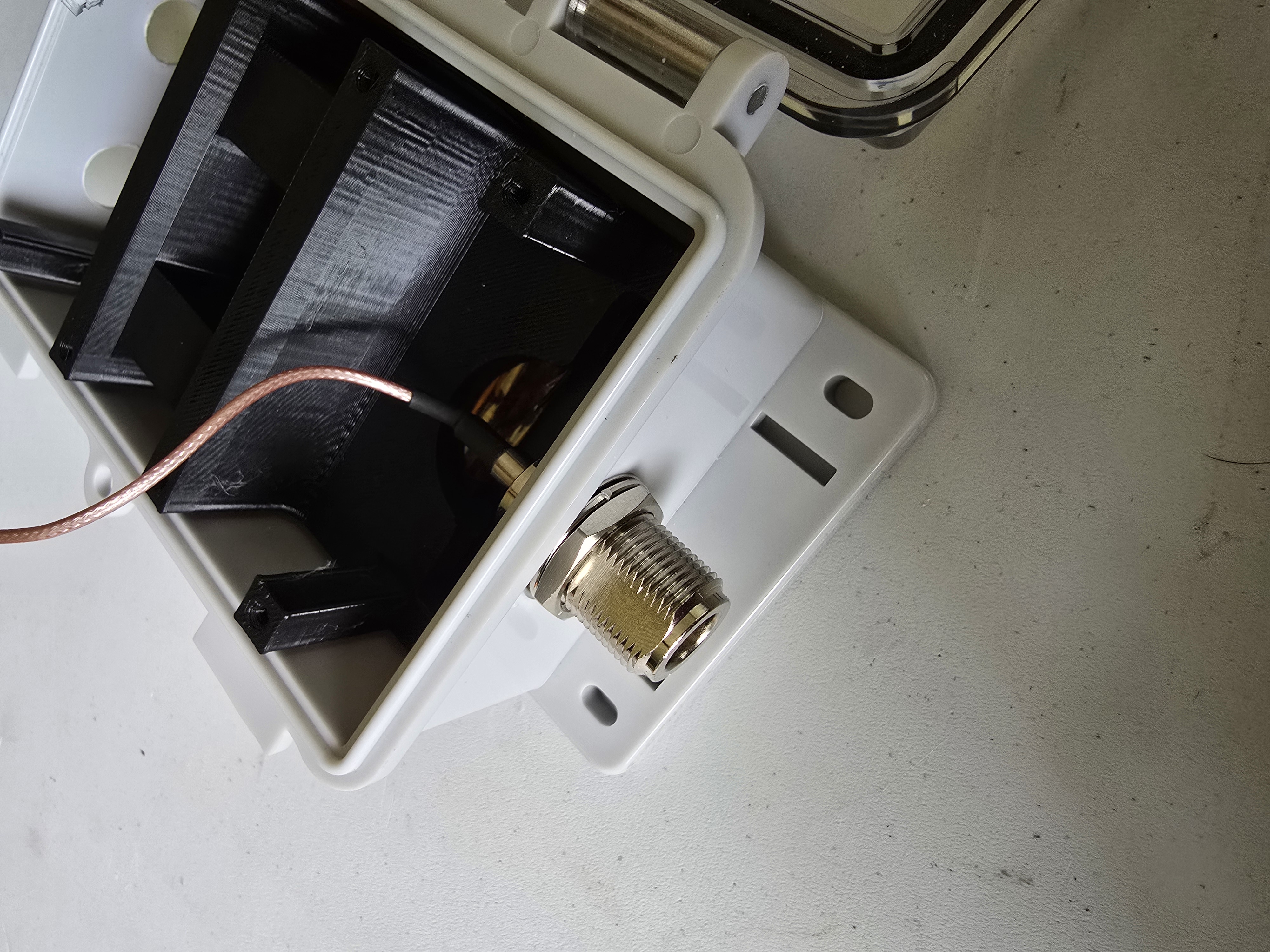
Connect Heltec T114 to Antenna Feedline and Battery.
Identify the LoRa connection on the board. It is a U.FL/IPEX connector, which is a very small, circular gold connector with a pin in the middle. When connecting IPEX antenna leads, make sure to have the cable end perfectly centered over top of the connector on the board, and then press straight down. Sometimes it is helpful to use a sturdy plastic tool to press down, but be sure that it doesn't slip and damage the board. These connectors are strong when pressed straight on, but can be fragile when wiggled or bent. So once these are connected, try to keep them from moving or disconnecting as much as possible.
Connect the IPEX to Type-N adapter to the LoRa terminal.
Route the Type-N bulkhead through the top hole and thread the washer and nut on from the outside. Secure tightly to prevent water ingress.
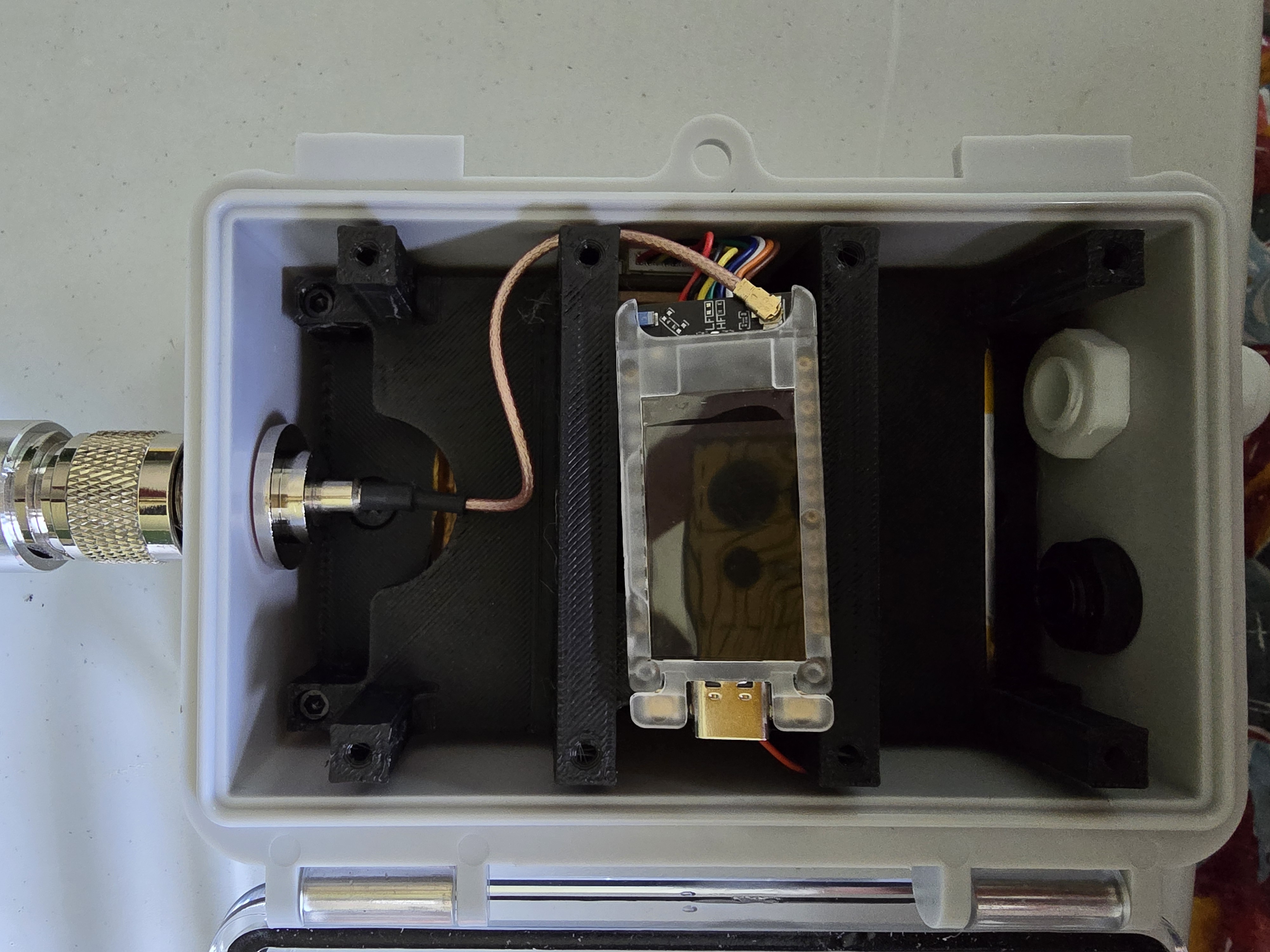
The antenna should be attached and threaded on before connecting the battery, as it will boot immediately. Connect the JST PH1.0 to the T114 BAT port.
With the battery lead fed through from the side, plug the connector into the BAT port, making sure not to confuse it with the SOLAR port.
-
Route the Solar Input.
Feed the USB-C solar panel cable through the bottom cable gland. Tighten the gland to create a waterproof seal around the cable. Plug the USB-C end directly into the WisBlock 4631's USB-C port.
If the USB-C cable is too thick- the included USB-C to Micro-USB cable can be cut, exposing two wires. These can then be terminated with a JST1.0 plug to connect directly to the board. The adapter can then pass the USB-C port outside of the enclosure, allowing the solar panel to be easily unplugged.
-
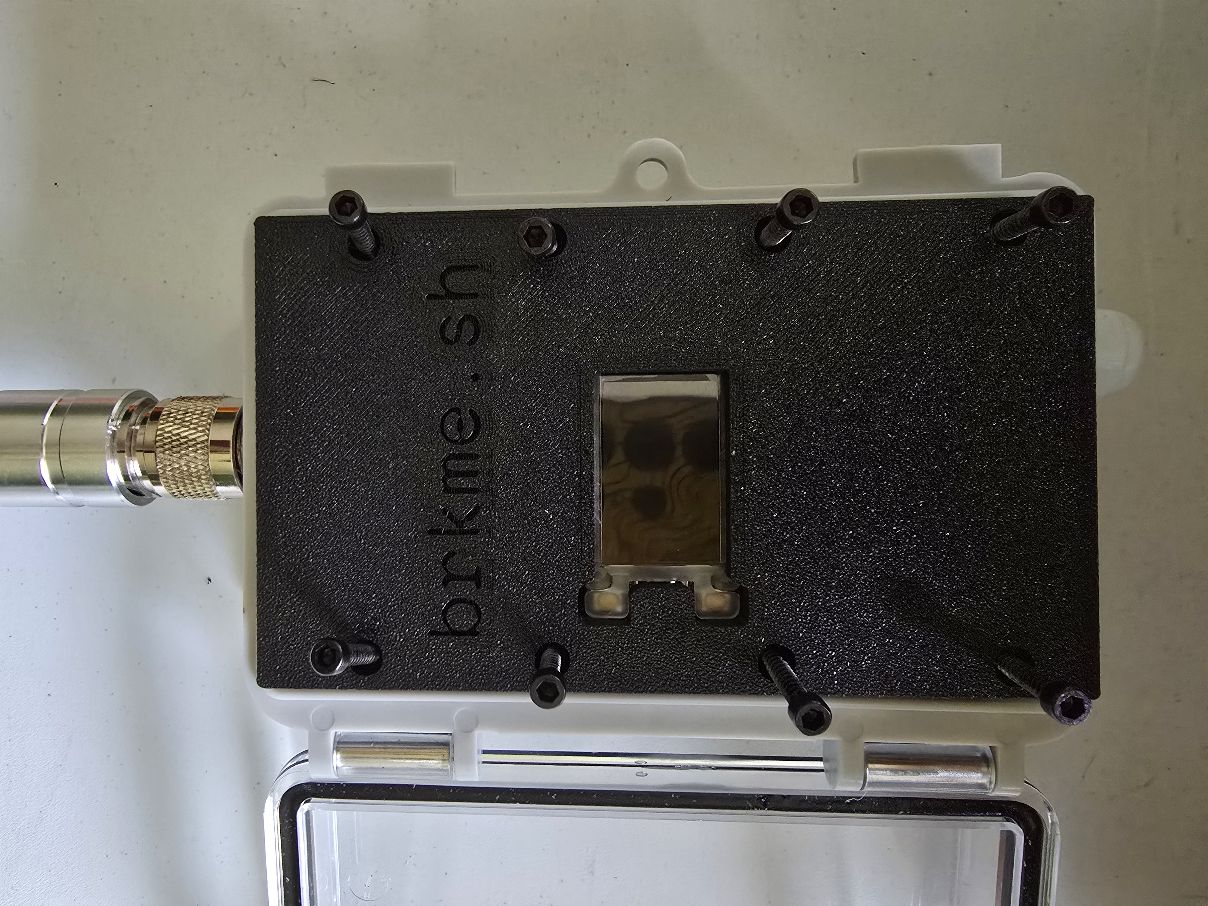
Secure Faceplate.
use the 8 screw holes to fasten the faceplate, centering the Heltec T114 in the space in the middle. Make sure the cables and coax are not pinched or resting on the edge of the enclosure.
-
Flash & Configure Firmware.
Connect the assembled node to your computer via USB-C and flash MeshCore firmware using the Official Flasher. Configure settings per the Recommended Settings in the Wiki:
- Preset: US/Canada 910.525MHz
- Hash Mode: 2-byte, 32 hop
- Bandwidth: 62.5kHz
- Spreading Factor: 7
Testing & Deployment
Before mounting permanently, verify everything works:
- All connections secure and waterproof
- Solar panel getting direct sunlight
- Node powered on (LED indicator visible)
- MeshCore app detects the node
- GPS lock acquired (if enabled)
For maximum range in the Berkshires, mount at elevation (rooftops, trees, mountaintops), face the solar panel south for all-day charging, and keep metal objects away from the antenna to reduce interference and noise floor.
Available Files
Troubleshooting
Node won't power on?
Check battery connection polarity. Ensure the battery isn't depleted — connect to USB-C power charger temporarily to wake the protection circuit.
Solar not charging?
Verify the USB-C cable is fully seated in the WisBlock 4631. Check that the cable gland isn't pulling on the cable when tightened.
Weak signal despite high placement?
Ensure the Type-N antenna is fully connected. Check that the IPEX connector inside is fully seated. Check the MeshCore app for noise floor (how much nearby radio frequency activity is impacting the signal) and SNR (Signal-to-Noise Ratio) statistics.
Enclosure condensation?
Add a waterproof breather valve to equalize pressure. Include silica gel packets inside to absorb moisture.